Crimping JST connectors with a 20$ amazon tool
This guide will detail a method very similar to the one described on this blog post by Alan Hawse. In his post, Alan uses an Engineer PA-09 crimping tool, which costs around 50 euro. I consider that to be too much if you’re just going to do a few dozen connections per year. As such, I bought this crimper on Amazon which costed me only 19 euro and can work with a few other types of connectors as well. I’ll apply a method somewhat similar to him, but applied to the tool I bought.
Firstly, it’s important to mention that “JST” stands for Japan Solderless Technology and they make around 50 thousand different types of connectors. As such, I am not able to write a completely general guide for all of them. This article will focus on JST-XH connectors, but you may be able to apply this information to other types of connectors as well.
The part that goes inside the JST connector looks something like this. Here, you can see that there are 3 distinct parts to it: A pair of large wings, a pair of slightly smaller ones and the end, which is that actually makes the plug. The large wings are the ones that bite onto the insulation and the small ones are the ones that bite into the wire. In the crimping process it is really important that the last part is left untouched. Otherwise, the male connector may not fit with its counterpart, or even worse, the metal part may not stay inside the plastic housing, which is a really common issue.
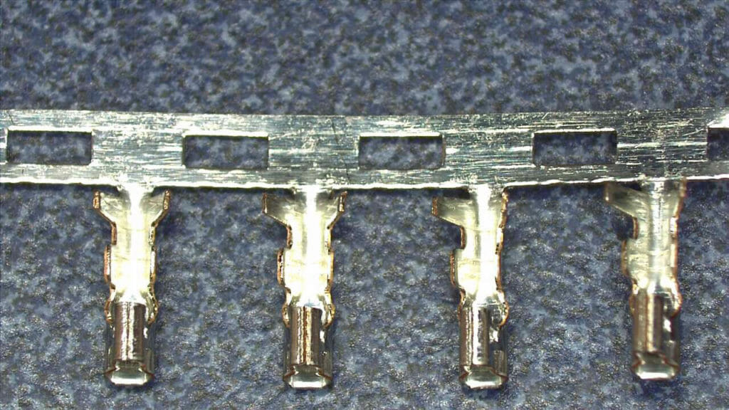 image: Metal part of the connector (source)
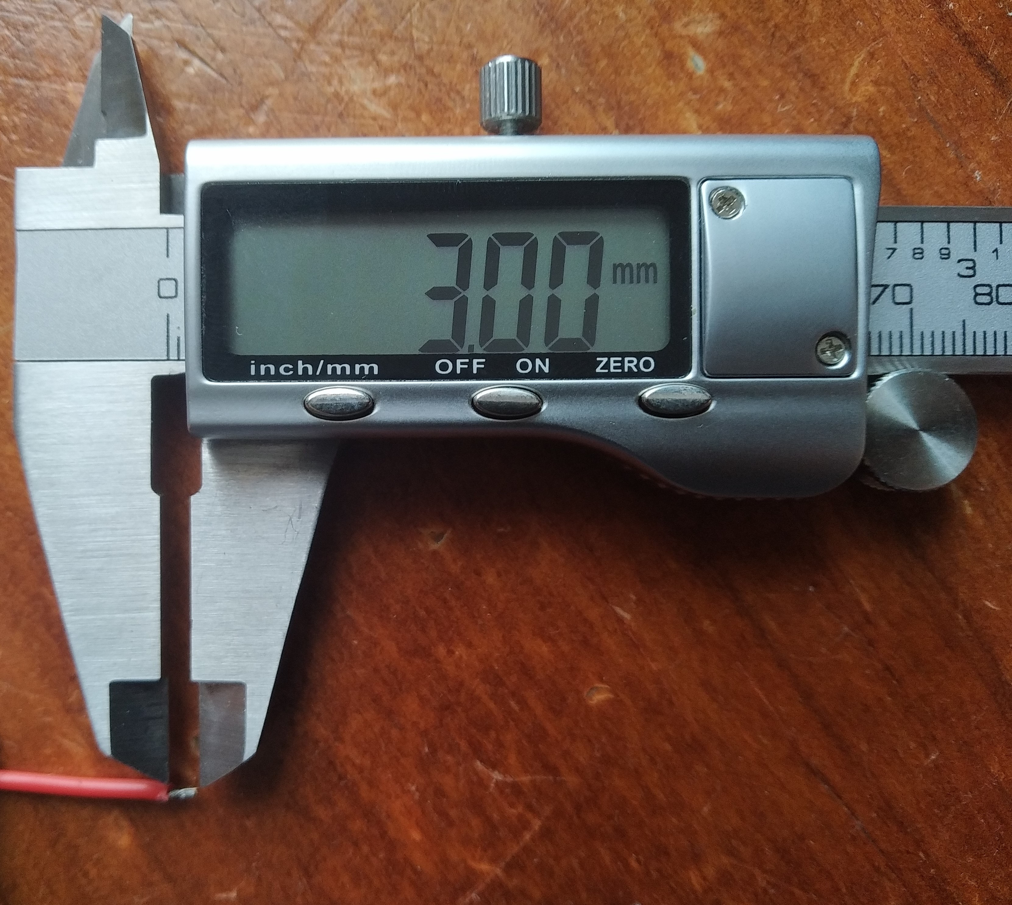
First, prepare the wire that you’ll be using for the connection. Strip 3 to 4mm of insulation off the end you want to put the connector in.
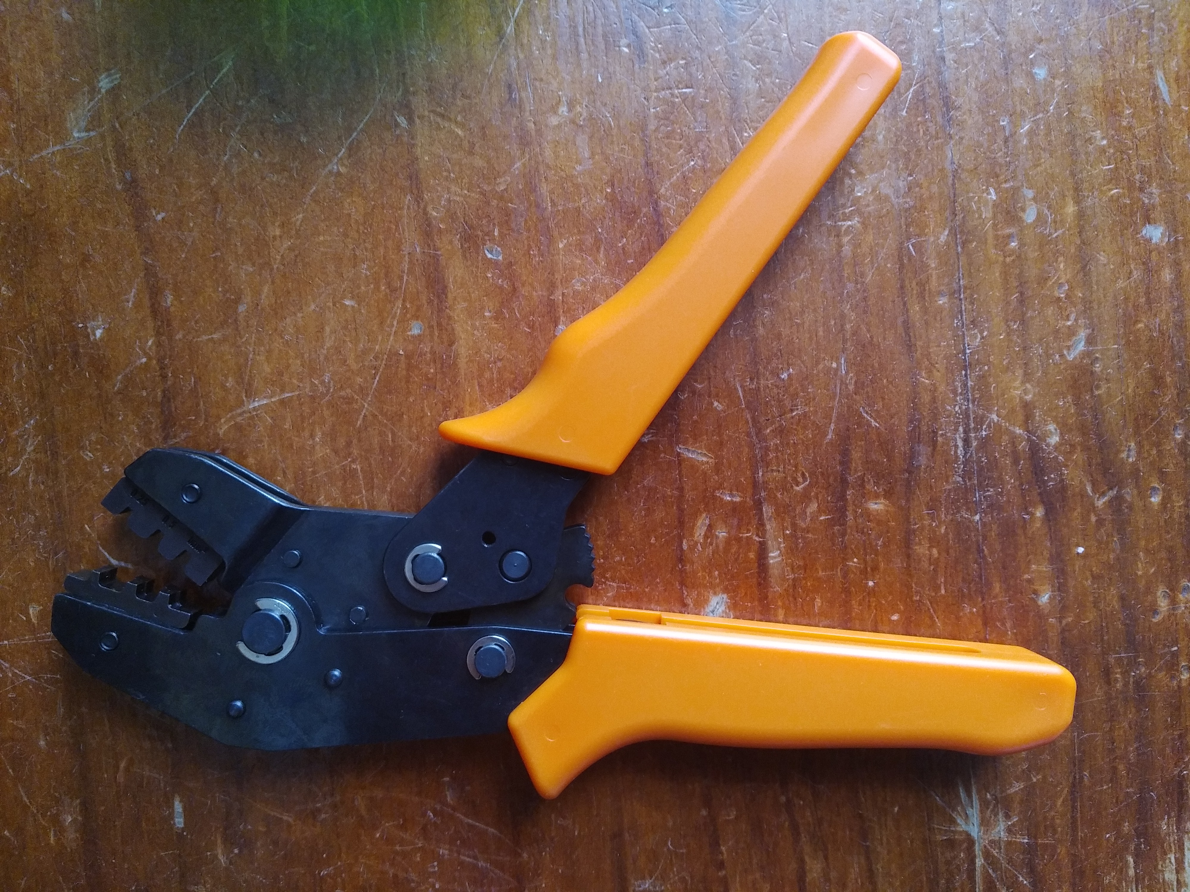
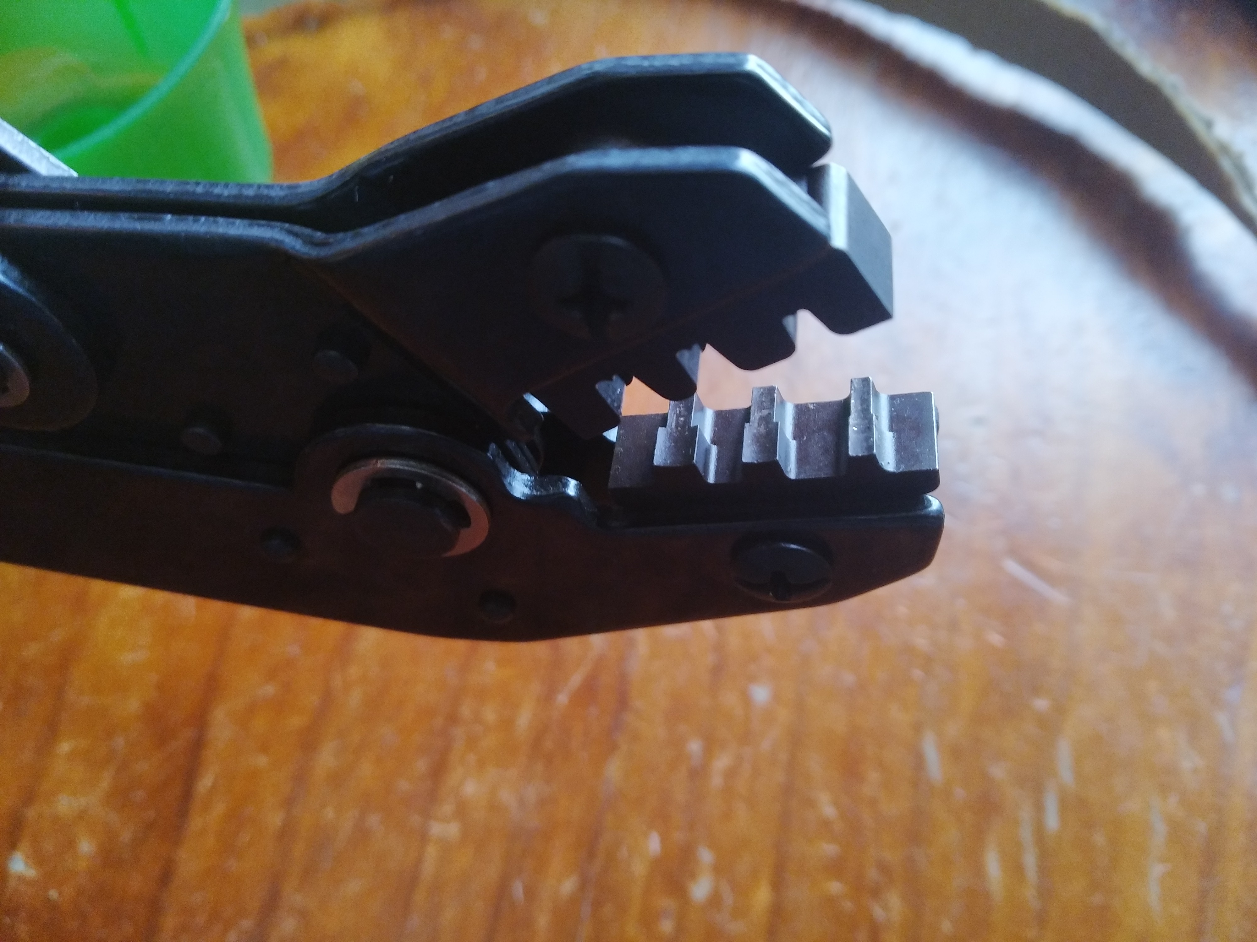
Next, we’ll be crimping the part that goes inside the connector onto the wire. Here’s the tool I will be using on this article. Amazon sells lots similar to this one, so it doesn’t matter much if yours isn’t exactly the same.
We will first crimp the large wings and then the small ones, working our way from the one end up to the connector side, as we do not want to bend (thus damage) the connector side. Using the end of the crimper tool as pliers, bend the large wings a bit inwards so that they will fit into the die for the next step.
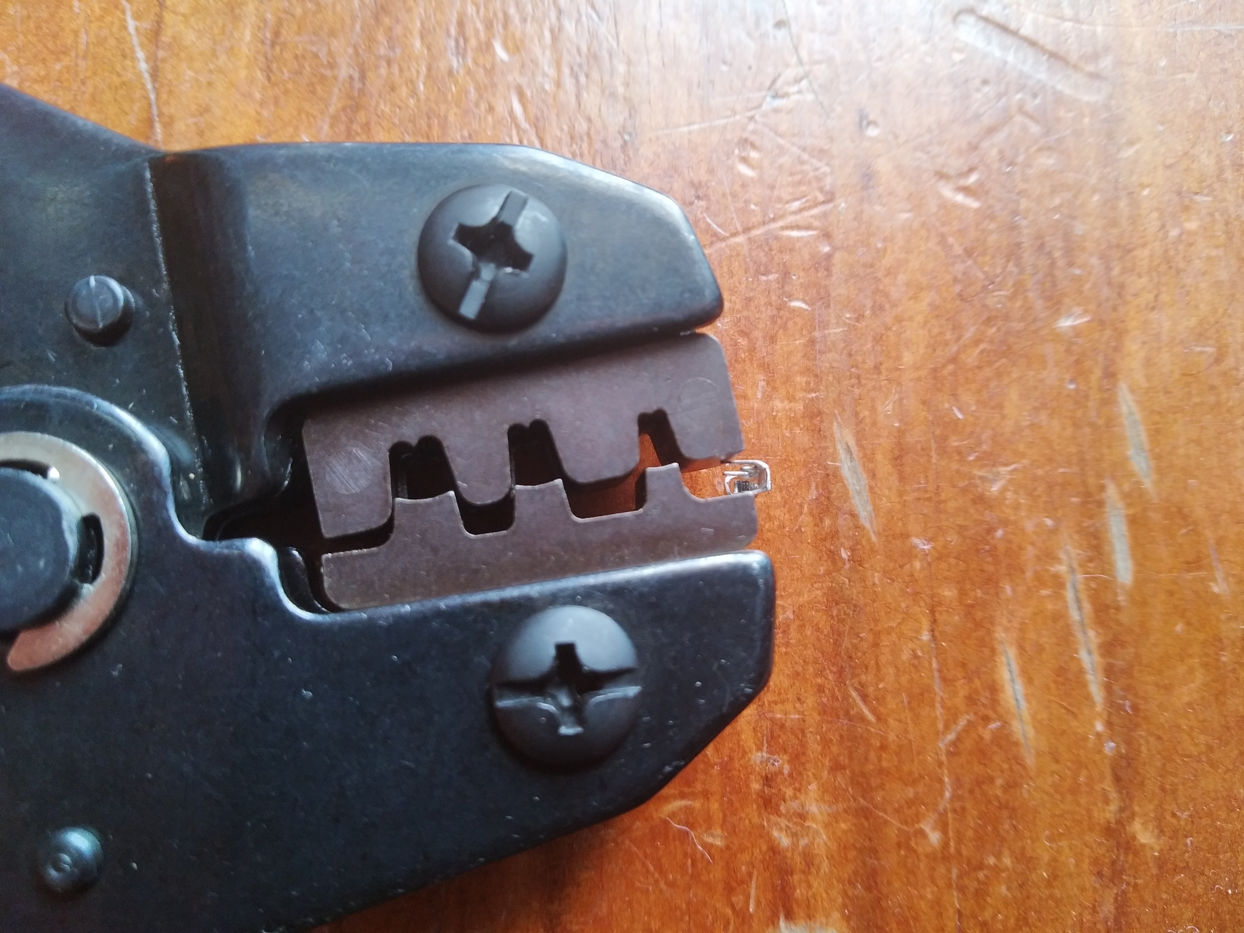
Now we’re going to bend the large wings into the insulation of the wire. First, notice that both sides of the crimping die are different. You’ll need to keep this in mind in the next steps.
We’ll be using a 1.9mm die to crimp the large wings.
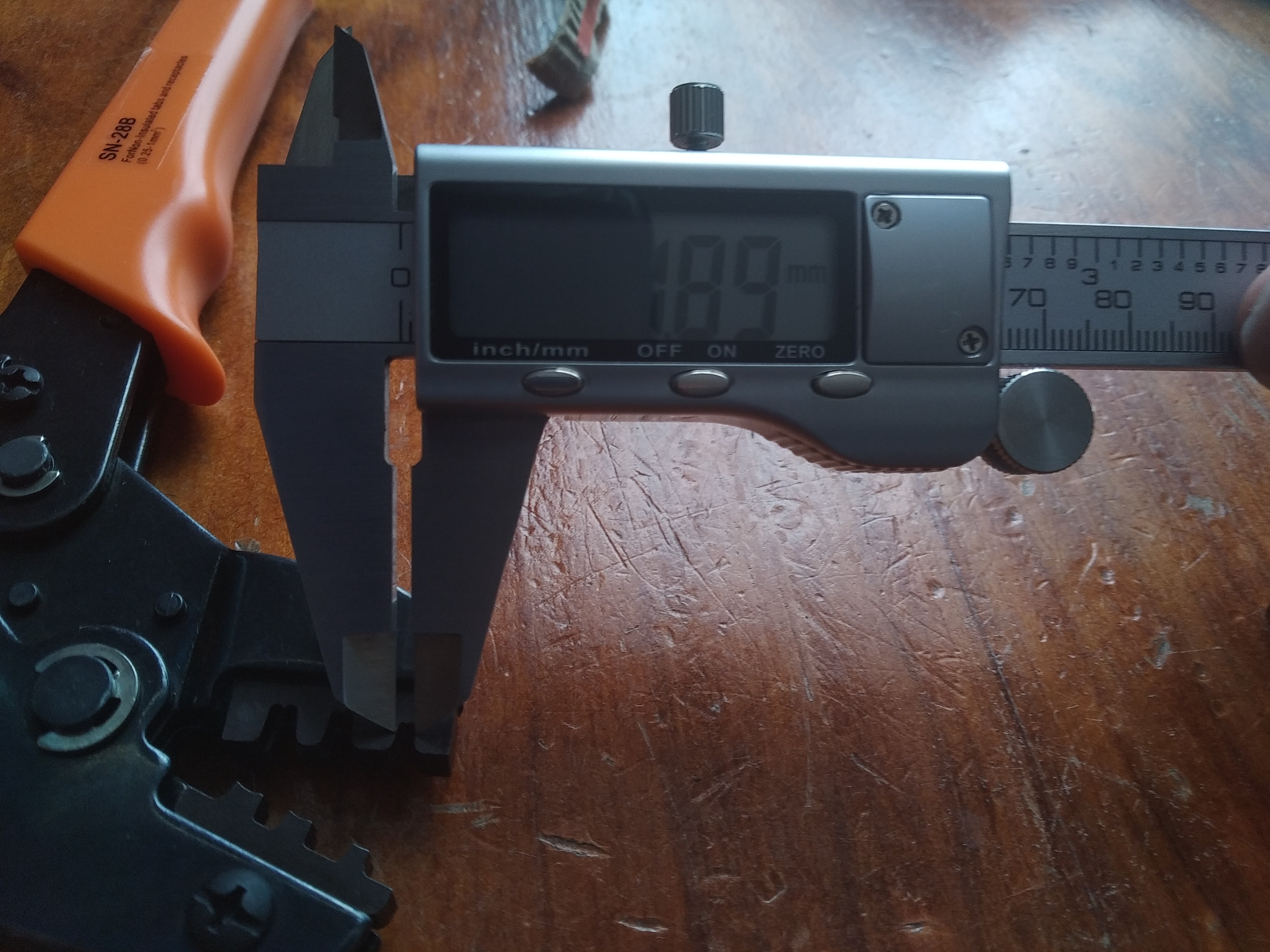
Place the metal part inside the die, with the wings facing the side that has the middle teeth, which is what will guide it onto itself when bending. Be careful to only include the large wings and nothing else inside the tool, as you do not want to bend anything else on this step.
Next, close the tool enough so that the metal part stays inside without moving around, and insert your wire. If your wire is thick like mine is, you may need to do this before putting the wings onto the tool. You want the wire insulation to reach only the large wings, not the small ones, like this:
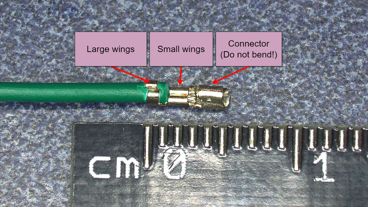 image: Length guide (original source)
You may now crimp the large wings. If everything went correctly, the metal part should be stuck to the wire.
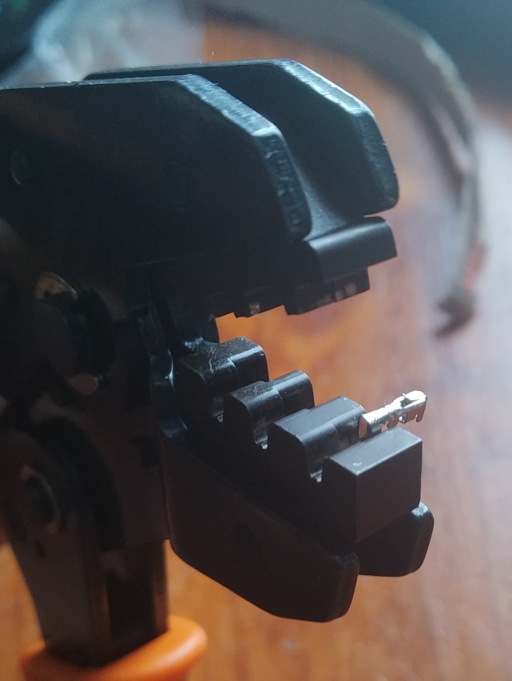
Now we will crimp the small wings onto the wire. Use the other (smaller) end of the crimping tool and insert it so that only the connector part stays outside of the tool. Be careful to not bend the small piece that sticks out of the connector, as that is what will keep the metal part inside of the connector housing.
That should be it! You can now insert the wires onto the male connector. If everything went correctly, they should click into place and not fall out.