The making of The Morse Device
I recently finished what I’m calling The Morse Device, a small handheld for learning morse code.

This project was part of an Electronics Systems subject I had last semester. I had to create an electronics system (hence the subject name) based around the MSP430G2ET, which itself is an evaluation board for the MSP430G2xx2, MSP430G2xx3, and MSP430F20xx Texas Instruments microcontroller lines. In our case, we had a MSP430G2553 available: A RISC MCU with incredibly low consumption, about 200 microamps at 1MHz, translating into around 0.4mW given 1.8V. However, it also has really low specs, with 16kB of flash memory, a maximum frequency of 16MHz and just 512 bytes of RAM. Designing a decent project around this processor was going to be a fun challenge.
As this was the second project of the subject, and I was a bit burnt out from finishing the first one (I’ll describe it at some point in another blog post…), I decided not to think too much about it, and make something I could comfortably finish without much hassle.
Of course, we didn’t only have the evaluation board to work with. We could ask the electronics department for components, and also had an Educational BoosterPack MKII board: A glorified 60€1 gamepad with a screen and some sensors. We had worked with it for the subject’s duration, so most people decided to base the project around it. However, I didn’t want to limit myself to using it, as not only would it degrade my project’s final mark (As I wouldn’t have made any board of my own), but it would also become contradictory with one of the objectives of the project which I set later.
The project’s evaluation criteria was based around how the microcontroller fit the idea used, and how well it was implemented. At first, I thought about remaking the Sokoban clone I made a while ago, but it didn’t sound particularly exciting nor original. Although making games on the device was certainly a possibility, I decided to try to come up with another idea, as most people in class were already thinking of making their own and most games I could think of didn’t particularly require that many MCU peripherals. While I was at it, I set another objective to use as little power as possible; After all, that is what the processor line is intended for.
This is where I would notice much later on in the project that not using the Boosterpack board was actually a really good decision, as the LCD it included consumed 100mW just for the backlight. Using that screen would’ve absolutely destroyed my consumption stats.
The components
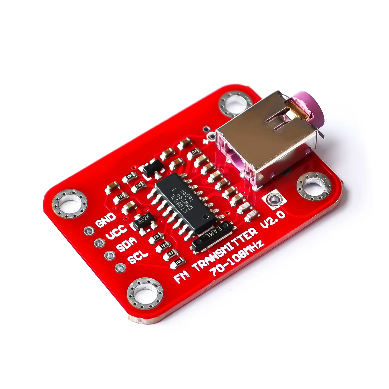
One evening, while rummaging through my components shelf, I found a KT0803L board, abandoned from an experiment from a few months ago.

As the image says, it’s a FM transmitter. It’s a really cool module, albeit one that is hard to source (I couldn’t find the chip in any distributor except in Aliexpress in the form of pre-mounted boards). With this module in hand and some days of thinking later, I came up with the idea of making a Morse code transmitter. Although I really liked this idea, the module didn’t want to cooperate, and I finally ended up deciding not to include it in the final project. It need a decently sized antenna to be usable, and it just wasn’t really worth it just to get one-way short-ranged radio transmission. However, I still stuck with the morse aspect of the idea, and decided to create a device that decoded whatever morse you input through a button.
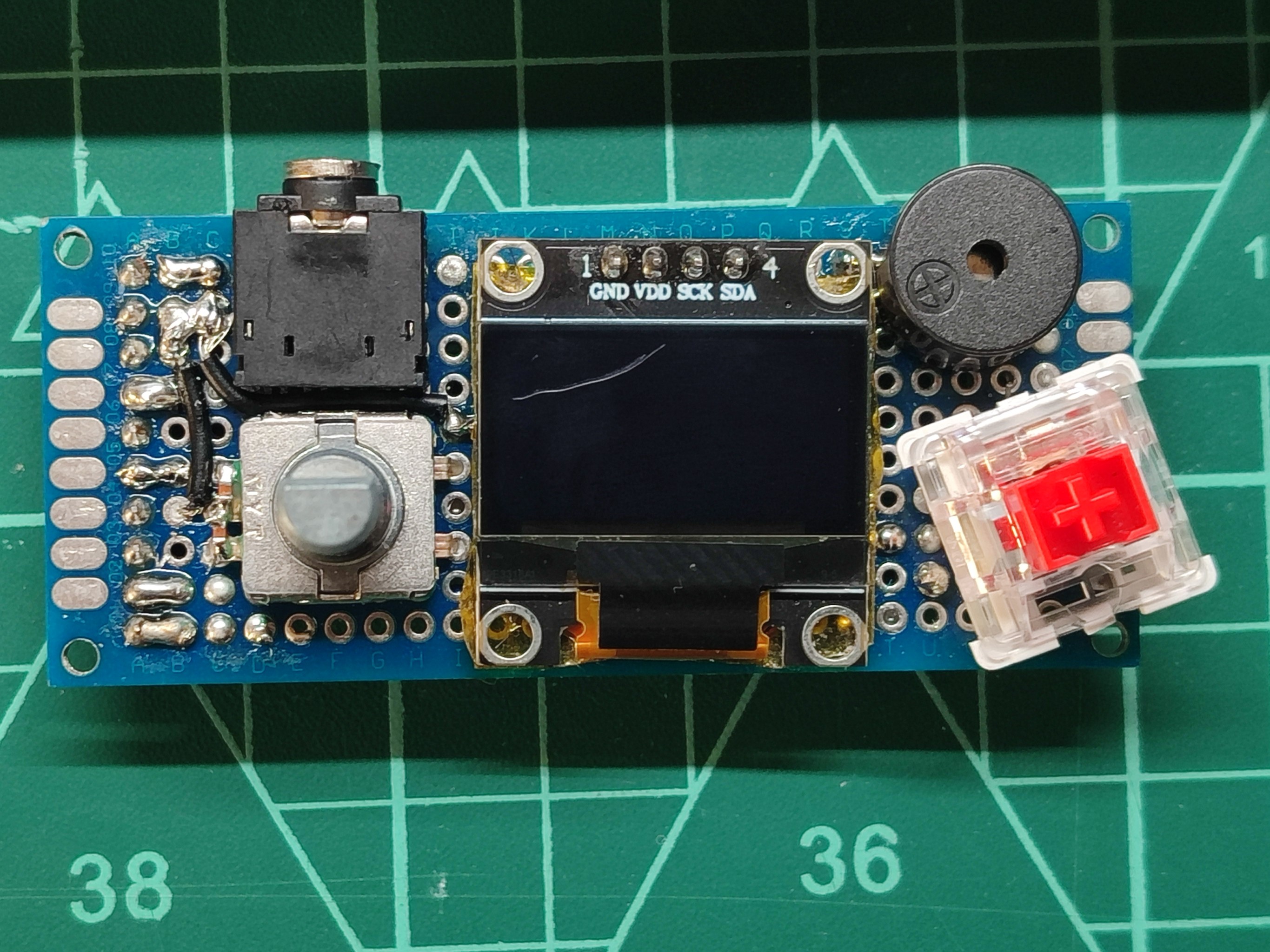
With that in mind, I grabbed a tactile button for the morse input, a small 0.96” OLED screen for the user interface, a rotary encoder for navigating through menus and selecting options and a buzzer to produce morse beeps.
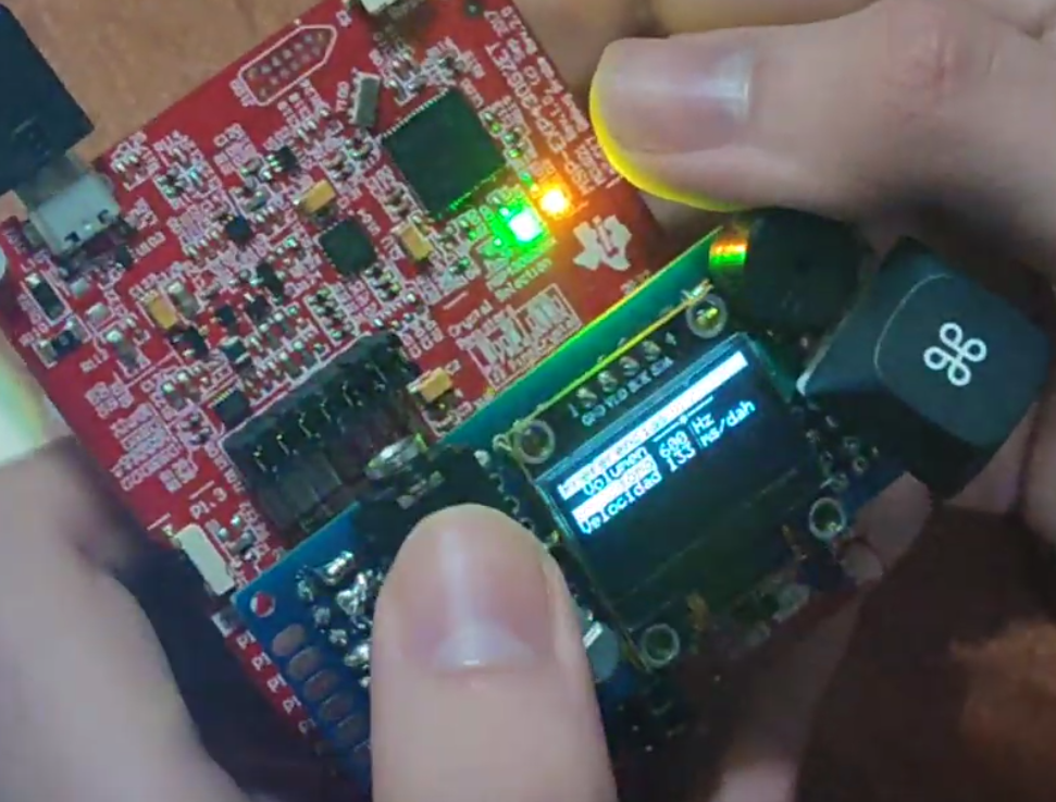
After a few hours’ worth of work I had a working prototype:
Incredibly mature, I know. This is the first video I took of the device in action, on January 19th.
I spent 2 more days working on the software, and then decided it was time to move on to soldering a real board.
The board
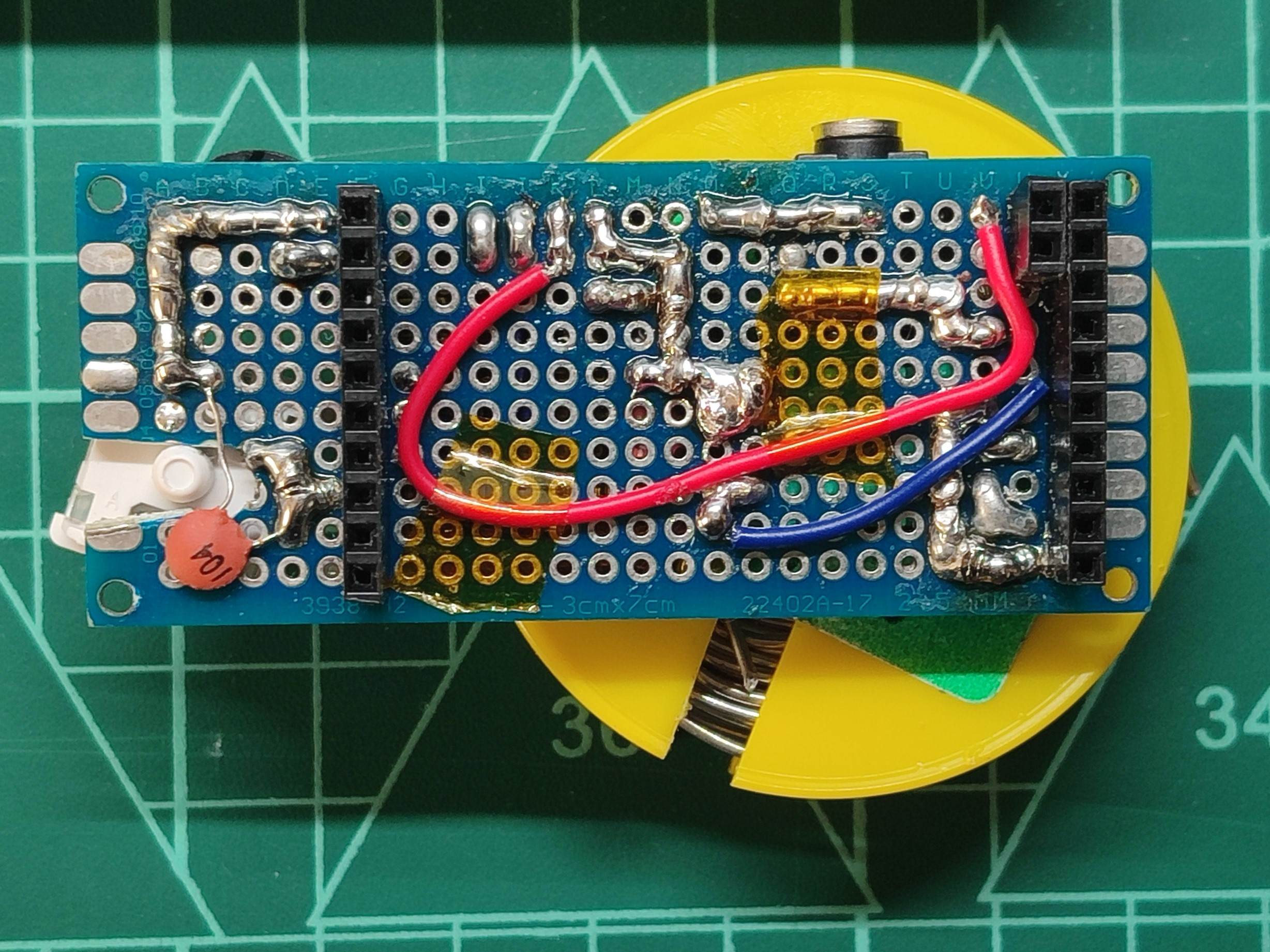
I didn’t want to spend more than a single day soldering as I knew I was going to get tired of it really quickly. Although I could’ve designed a PCB, shipping would’ve taken so long I was worried I wouldn’t finish the project in time. I grabbed a 3x7cm perfboard and got to work getting all the components in place. Not long after I had this:

By this time I had also added a second audio output option, in the form of a 3.5mm aux port. Since 3.3v was a bit much to output through it, I used two diodes in series to lower it to around 1.4v. Of course, this is a complete hack, but it worked somewhat fine. In retrospect I should’ve used another diode more as putting the output signal’s duty cycle any value higher than 10% completely annihilates your hearing.
All that was missing was the morse input button. I had a few leftover mechanical switches from my keyboard, so I used one for it. The only issue was getting the MX footprint match the perfboard: I had to drill a hole for the plastic underside to fit, and also had to place it on an awkward angle to get the pins to match the holes:

And here are some nicer pictures of the finished board:


The case
After working on the hardware, I decided to spend that same weekend’s sunday to create a plastic cover for the device, so at least the user-facing side wasn’t covered with solder and wires.
I designed the case using Fusion, and it took me the entire day to get it just right, but in the end it ended up somewhat nice.

Here are the three iterations, from first (upmost) to last. The first one was printed with humid filament which I dried for the second iteration. The second one had an extra large switch hole and very thin external perimeter walls. The last iteration was perfect: No stringing, thick walls, well measured holes. I also removed the extra holes I put for the screen because the screws couldn’t come through the other side anyways, as the perfboard was in the way. For mounting I used M2.5 screws along with some nuts to hold the board in place.
The final result
(Video is in Spanish, but there are captions available).
Future work
I’ve thought of putting an upgraded version of this circuit into a PCB, removing the need for the evaluation board. The device itself is not that useful, but I could practice my board design and SMD soldering skills that way. Even thought of selling this as a kit, as gadget SMD soldering kits aren’t very common and maybe some people could be interested on that. Feel free to let me know over on Discord if you like that idea.
Sorry for the photo quality on this post. I’ll try to be more careful and take better pictures next time.
Thanks for reading, and until next time.
-
Technically 30$, but that’s without the distributor quota, 20€ Fedex shipping and 21% VAT. ↩